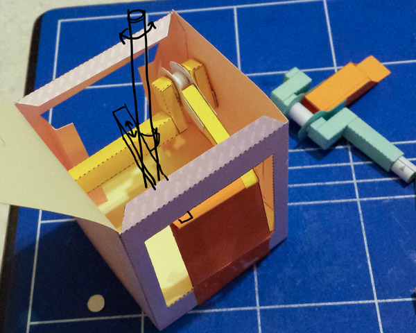
There are two main parts to the type 2 Reciprocating Rotating Vertical Shaft mechanism (RRVS-t2) The first part, which I mentioned in the previous post on the subject, is the pair of paper straps wrapped around the vertical shaft that do the actual turning. These straps are glued to a beam which moves back and forth to rotate the shaft clockwise then anti-clockwise.
The second part of the mechanism is the part that drives the beam back and forth. I’m using a crank for this. You can see the first crank I created to the right of this picture. It worked but took up too much space so the vertical shaft didn’t fit in the box.

The redesigned crank fitted into the box is about half the width of the first version. Actually probably narrower than it needs to be. The crank connects via a linkage to a hinged plate at the front of the box.
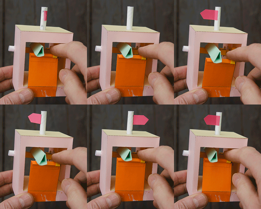
 The box is closed and the beam is connected between the vertical shaft and the hinged plate. The individual parts of the mechanism work nicely but I need to work on how everything is lined up. Moving the hinged plate back and forth by hand you can see that the vertical shaft rotates almost a complete revolution in each direction.
Next step line everything up properly and fit it neatly into the box complete with drive handle.


